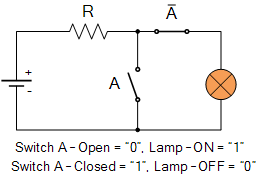
Switch Diagram Of Not Gate
Gate gates switch diagram representations kzoo cs edu Not circuit gate inverter logic diagram schematic gates diodes practical resistors bipolar composed exclusively transistors operation The not gate
NOT Gate Circuit Diagram and Working Explanation
Gates logic transistor What is a not gate? Logic not function
Gate transistor transistors designing diode circuitdigest manoj kumar diodes
Gate not circuit diodes gates diode digital logic switch steering electric current back circuits feee two transistor voltage instrumentationtools positionTransistor not gate logic gates electronics digital circuit using switch table truth circuits switches tutorial off moteino base doorbell input Gate representationsNot gate circuit diagram and working explanation.
Understanding logic gates at transistor level : not gateNot function logic switch boolean representation digital gates Figure 3-5. two switch as an and gateLogic gates using switch – and, or, not » pija education.

Gate ic not circuit 74ls04 pinout logic diagram gates input working xnor chip nor hex circuitdigest electronic electrical engineering diagrams
Gate switchLogic not gate tutorial with logic not gate truth table Designing not gate using transistorsGate not circuit switching switch open logic symbol lamp when will illustrates glow go off figure.
.


NOT Gate Circuit Diagram and Working Explanation

LOGIC GATES USING SWITCH – AND, OR, NOT » PIJA Education

Designing NOT Gate using Transistors

The NOT Gate | Logic Gates | Electronics Textbook

Understanding Logic gates at transistor level : Not Gate | VLSI

What is a NOT Gate? - Logic Symbol & Truth Table - Circuit Globe

Figure 3-5. Two switch as an AND gate

FEEE - Fundamentals of Electrical Engineering and Electronics: The NOT gate

Gate Representations